The most important concept to understand is that lean mixtures, such as at idle and steady highway cruise, take longer to burn than rich mixtures; idle in particular, as idle mixture is affected by exhaust gas dilution. This requires that lean mixtures have "the fire lit" earlier in the compression cycle (spark timing advanced), allowing more burn time so that peak cylinder pressure is reached just after TDC for peak efficiency and reduced exhaust gas temperature (wasted combustion energy). Rich mixtures, on the other hand, burn faster than lean mixtures, so they need to have "the fire lit" later in the compression cycle (spark timing retarded slightly) so maximum cylinder pressure is still achieved at the same point after TDC as with the lean mixture, for maximum efficiency.
The centrifugal advance system in a distributor advances spark timing purely as a function of engine rpm (irrespective of engine load or operating conditions), with the amount of advance and the rate at which it comes in determined by the weights and springs on top of the autocam mechanism. The amount of advance added by the distributor, combined with initial static timing, is "total timing" (i.e., the 34-36 degrees at high rpm that most SBC's like). Vacuum advance has absolutely nothing to do with total timing or performance, as when the throttle is opened, manifold vacuum drops essentially to zero, and the vacuum advance drops out entirely; it has no part in the "total timing" equation.
At idle, the engine needs additional spark advance in order to fire that lean, diluted mixture earlier in order to develop maximum cylinder pressure at the proper point, so the vacuum advance can (connected to manifold vacuum, not "ported" vacuum - more on that aberration later) is activated by the high manifold vacuum, and adds about 15 degrees of spark advance, on top of the initial static timing setting (i.e., if your static timing is at 10 degrees, at idle it's actually around 25 degrees with the vacuum advance connected). The same thing occurs at steady-state highway cruise; the mixture is lean, takes longer to burn, the load on the engine is low, the manifold vacuum is high, so the vacuum advance is again deployed, and if you had a timing light set up so you could see the balancer as you were going down the highway, you'd see about 50 degrees advance (10 degrees initial, 20-25 degrees from the centrifugal advance, and 15 degrees from the vacuum advance) at steady-state cruise (it only takes about 40 horsepower to cruise at 50mph).
When you accelerate, the mixture is instantly enriched (by the accelerator pump, power valve, etc.), burns faster, doesn't need the additional spark advance, and when the throttle plates open, manifold vacuum drops, and the vacuum advance can returns to zero, retarding the spark timing back to what is provided by the initial static timing plus the centrifugal advance provided by the distributor at that engine rpm; the vacuum advance doesn't come back into play until you back off the gas and manifold vacuum increases again as you return to steady-state cruise, when the mixture again becomes lean.
The key difference is that centrifugal advance (in the distributor autocam via weights and springs) is purely rpm-sensitive; nothing changes it except changes in rpm. Vacuum advance, on the other hand, responds to engine load and rapidly-changing operating conditions, providing the correct degree of spark advance at any point in time based on engine load, to deal with both lean and rich mixture conditions. By today's terms, this was a relatively crude mechanical system, but it did a good job of optimizing engine efficiency, throttle response, fuel economy, and idle cooling, with absolutely ZERO effect on wide-open throttle performance, as vacuum advance is inoperative under wide-open throttle conditions. In modern cars with computerized engine controllers, all those sensors and the controller change both mixture and spark timing 50 to 100 times per second, and we don't even HAVE a distributor any more - it's all electronic.
Now, to the widely-misunderstood manifold-vs.-ported vacuum aberration. After 30-40 years of controlling vacuum advance with full manifold vacuum, along came emissions requirements, years before catalytic converter technology had been developed, and all manner of crude band-aid systems were developed to try and reduce hydrocarbons and oxides of nitrogen in the exhaust stream. One of these band-aids was "ported spark", which moved the vacuum pickup orifice in the carburetor venturi from below the throttle plate (where it was exposed to full manifold vacuum at idle) to above the throttle plate, where it saw no manifold vacuum at all at idle. This meant the vacuum advance was inoperative at idle (retarding spark timing from its optimum value), and these applications also had VERY low initial static timing (usually 4 degrees or less, and some actually were set at 2 degrees AFTER TDC). This was done in order to increase exhaust gas temperature (due to "lighting the fire late") to improve the effectiveness of the "afterburning" of hydrocarbons by the air injected into the exhaust manifolds by the A.I.R. system; as a result, these engines ran like crap, and an enormous amount of wasted heat energy was transferred through the exhaust port walls into the coolant, causing them to run hot at idle - cylinder pressure fell off, engine temperatures went up, combustion efficiency went down the drain, and fuel economy went down with it.
If you look at the centrifugal advance calibrations for these "ported spark, late-timed" engines, you'll see that instead of having 20 degrees of advance, they had up to 34 degrees of advance in the distributor, in order to get back to the 34-36 degrees "total timing" at high rpm wide-open throttle to get some of the performance back. The vacuum advance still worked at steady-state highway cruise (lean mixture = low emissions), but it was inoperative at idle, which caused all manner of problems - "ported vacuum" was strictly an early, pre-converter crude emissions strategy, and nothing more.
What about the Harry high-school non-vacuum advance polished billet "whiz-bang" distributors you see in the Summit and Jeg's catalogs? They're JUNK on a street-driven car, but some people keep buying them because they're "race car" parts, so they must be "good for my car" - they're NOT. "Race cars" run at wide-open throttle, rich mixture, full load, and high rpm all the time, so they don't need a system (vacuum advance) to deal with the full range of driving conditions encountered in street operation. Anyone driving a street-driven car without manifold-connected vacuum advance is sacrificing idle cooling, throttle response, engine efficiency, and fuel economy, probably because they don't understand what vacuum advance is, how it works, and what it's for - there are lots of long-time experienced "mechanics" who don't understand the principles and operation of vacuum advance either, so they're not alone.
Vacuum advance calibrations are different between stock engines and modified engines, especially if you have a lot of cam and have relatively low manifold vacuum at idle. Most stock vacuum advance cans aren’t fully-deployed until they see about 15” Hg. Manifold vacuum, so those cans don’t work very well on a modified engine; with less than 15” Hg. at a rough idle, the stock can will “dither” in and out in response to the rapidly-changing manifold vacuum, constantly varying the amount of vacuum advance, which creates an unstable idle. Modified engines with more cam that generate less than 15” Hg. of vacuum at idle need a vacuum advance can that’s fully-deployed at least 1”, preferably 2” of vacuum less than idle vacuum level so idle advance is solid and stable; the Echlin #VC-1810 advance can (about $10 at NAPA) provides the same amount of advance as the stock can (15 degrees), but is fully-deployed at only 8” of vacuum, so there is no variation in idle timing even with a stout cam.
For peak engine performance, drivability, idle cooling and efficiency in a street-driven car, you need vacuum advance, connected to full manifold vacuum. Absolutely. Positively. Don't ask Summit or Jeg's about it – they don’t understand it, they're on commission, and they want to sell "race car" parts.
Courtesy John Hinckley
Retired GM/Chrysler Engineer
ENGINE HP CARB. TRANS. COMP. CODE
225 V6 155 2-BBL AT/MT 9.00:1 LH
225 V6 --- 2-BBL AT/MT 7.60:1 LJ(export)
330 V8 250 2-BBL MT 9.00:1 Ql
330 V8 250 2-BBL MT 9.00:1 QJ(HD clutch)
330 V8 --- 2-BBL MT 8.30:1 QK(export)
330 V8 250 2-BBL AT 9.00:1 QA
330 V8 250 2-BBL AT 9.00:1 QB(with A/C)
330 V8 --- 2-BBL AT 8.30:1 QC(export)
330 V8 315 4-BBL MT 10.25:1 QV
330 V8 315 4-BBL MT 10.25:1 QX(HD clutch)
330 V8 --- 4-BBL MT 8.30:1 QY(export)
330 V8 315 4-BBL AT 10.25:1 QN
330 V8 315 4-BBL AT 10.25:1 QP(with A/C)
330 V8 --- 4-BBL AT 8.30:1 QO(export)
400 V8 345 4-BBL MT 10.25:1 QW
400 V8 345 4-BBL AT 10.25:1 QR
Early 400
Built 1965 - 1967.
Late 400
Built 1968 - 1969.
The short stroke 1965-67 400s are awesome motors, but in 68-69 Olds attempted to reduce emissions by using a reduced bore to minimize combustion chamber quench area and thus lower unburned hydrocarbons (emissions controls actually started in 1968 on 49-state cars). Note that this decision to go with a smaller bore was also due in no small part to the desire to use a common crankshaft with the new 455 in 1968 as well. The result is a terribly undersquare motor (3.870 bore x 4.125 stroke) which won't rev very well. This is the worst bore-to-stroke ratio of any American V8 from the modern era.
One limiting factor to your buildup will be the small bore size of your later 400, which can shroud larger valves. One great way to gain yourself some horsepower is to move up to a 455 shortblock with your stock "C" heads; more cubic inches, and the large valves will breathe even better.
The story on the change from the early 400 to the 68-69 400 was due to design changes to start limiting emissions and with the longer stroke they picked up more torque which lead to more power at lower rpm. Thus their early attempt to reduce gas consumption and increase mileage with lower emission. Plus the redesign of the internals which now shared the same crank and rods as the 455's.
I recall reading that the undersquare design of the 400 and 455 in 1968 was intended to reduce the quench area in the combustion chamber to reduce emissions. Apparently, the walls of the combustion chamber are cooler than the rest (makes sense) and fuel can condense out there and lead to incomplete burning and thus higher HC and CO emissions. By making the bore smaller, the surface area of the combustion chamber is, by definition, reduced.
Of course, while that was the published rationale, I suspect that this decision had more to do with commonality of the expensive crank forging between the 400 and 455 than anything else. Since Olds likely expected to sell many more 455s than 400s, redesigning the 400 to use the 455 crank and rods probably made a lot of financial sense.
[ Thanks to Rob Thomas, Bob Barry, Joe Padavano for this information ]
Rev Potential, Limit
The early 400 engines rev higher than any other big block. They will rev higher than a 425. Got a little less piston mass. These things will turn almost 7000 RPM.
[ Thanks to Jim Chermack for this information ]
Various Information
Engine Casting Number Deciphering
This chart will help you decipher what engine type your have in your Cutlass. While the data is somewhat inconclusive, it provides an overall point of reference for engine decoding. If you have information to fill in the gaps or see an error, please contact me.
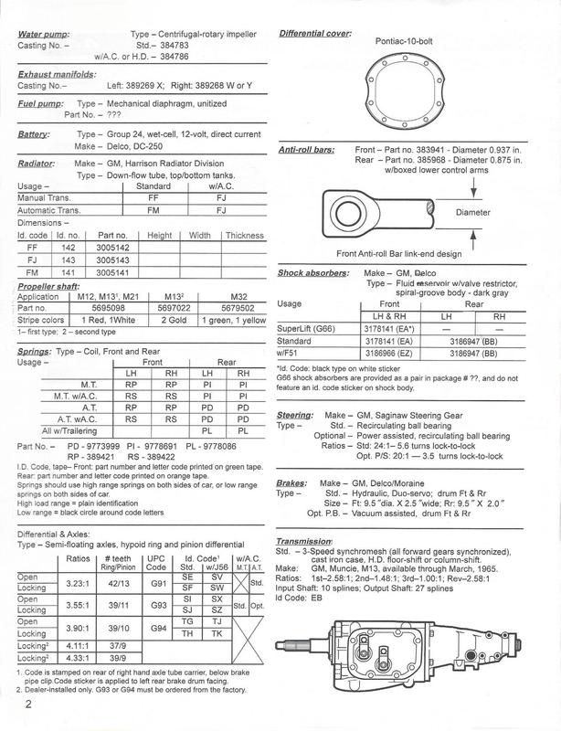
In order to figure out what block you have in your car, you must locate the Casting Number. This can be found at the front of the engine on a flat surface behind the timing chain area. ( See picture at top of page) Look to the right (if facing the fan) of the oil filler tube and you will see the stamping on the block. This number should match one of those below. Remember, big blocks are identified by a letter for the ID Code, while small blocks carry a number.
Big Block reference chart:
Casting NumberID CodeCIDYear(s) ProducedNotes
381917A4251965B Bodies (big cars) only
386525Red A 425
389298Bronze B4001965 One year only 442 motor. The lifter cam angle bank was 45 degrees
and changed to 39 degrees in 1966
389244D4251966 - 1967Big car engine. Toronado is different internally.
390925E4001966 - 1967 Heads were changed to a 39% bank from the 1965 45% bank.
396021F4551968 - 1972Most common big block. Two types of "F" letters: stick type, and one with two vertical hangers and a base.
396021Fa 4551972 - 1976Very common casting
396026G 4001968 - 1969442 and Vista Cruiser
231788L4551976 Motorhomes (1973 - 1978) maybe marine use also.
Small Block Reference chart:
Casting NumberID CodeCIDYear(s) ProducedNotes
38191713301964
38191723301965
39555823501968 - 1970
3 330
4
5
395558 3501973 - 1974
2A 2601976 - 1981Solid main webs for 2A's only? At least for '76
557751 2B 26019?? - 1981Windowed main webs for 2B's only?
3A
5572654A4031977Solid main webs possibly
5539904A4031977Solid main webs possibly
5549904A4031977Solid main webs possibly
5572654B4031977 - 1979Windowed main webs always.
D3350Diesel
Information gathered from various books and individuals. Credit goes out to the FAQ compilers at 442.com
(65 & 66)
(65 Only)
Fuel Lines: 442 3/8 inch Cutlass / F-85 5/16 inch
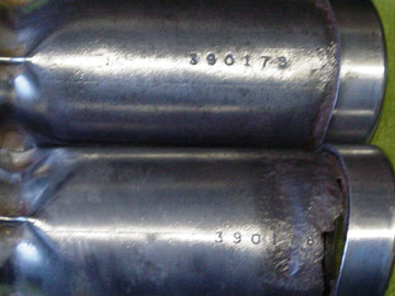
These are the original tail pipes from my original 65. They are stamped on the top.
An "in coil" air bag is all you need, and you only need one, in the right (passenger side) spring. Air pressure in the bag is determined by rear ride height, tire size and pressure. Wheel hop can be caused by weak upper control arms, rear ride height incorrect (usually too high) causing pinion angle to be incorrect (using these no hop bars will almost certainly change pinion angle). Rather than using the no hop bars might as well use adjustable uppers, because all your doing with the no hop bars is changing the geometry where the uppers and lowers intersect. Your moving this imaginary line rearward, so you get a better instant center, this allows the rear axle to plant, rather than just squat .One other thing you might check is the condition of the body mounts, and bolts at the rear of the frame rails, forward of the rear wheels. Bad bushings, broken/loose bolt, especially passenger side will cause frame flex. Also you could replace the pad on the frame directly above the axle, with a mount like the 64`s had, would really take the spring out of your frame.
Now with all that said, get a bag, take a 1/2 hour, save your pinion angle, get rid of your hop.
Mike Dulak
Auxillary Ground ( small black wire from the battery ground terminal ) :
These cars did have the auxillary ground to the inner skirt, just ahead of the steering box. The reason for it was to serve as the ground circuit for the front lights etc. In Jasens case (melted the small ground wire) the cause, and effect are obvious, along with the question, why did it start after you cut the ground jumper?? The cause was a bad connection at the block from the negative side of the battery. There is no other explanation, period! What happened is, you turned the key to start, there was first the solenoid being energized, no problem for either the main ground to the block, even with a bad connection, or the auxillary jumper to the skirt. But now that the solenoid is closed, the two terminals are asking for mega amps, the little jumper that had less resistance than the main, couldn`t handle the load, fried !! Now the large cable to the block is connected, but because of corrosion, paint, or just loose, has a high resistance, but is still in the circut, when the high amperage is drawn thru the only path it has, it will clear the route by actually fusing a link the size it needs, or, open the circuit by melting. Did you ever weld with car batteries, ever touch jumpers together, hell of an arc. The engine block, in this case, is nothing but an extension of the negative battery cable terminating at the starter. Gotta complete the circuit !!!
Here`s one for ya! this was brought in to me for repair in the early 70`s
Customer:
Tried starting car, turned over like dead/low battery, smoke from under hood, under dash.
I opened hood, checked battery connections (battery located pass side) noticed ground jumper to pass fender was blistered,most insulation melted. Further inspection located antenna cable melted, burnt in half. Same culprit, different reason. The car had been in an accident, radiator support repaired, battery and neg cable replaced, fender replaced. for one reason or another ground cable was never cleaned properly to the block, the fender before installation was cut in with primer/paint, then mounted and finish paint applied. The combination of all that new paint, and loose ground to the block, led to high resistance at the main ground, no grounding of the fender to the body, other than thru the aux. jumper from the neg. cable, and the antenna ground to the radio, from the radio frame thru the dash/ cowl metal, to that poor little strap on the back of the engine head.
So back to the original question that started this post "What`s the purpose/benefit of the ground strap"
YOUR CAR CAN`T LIVE WITHOUT IT !!!!!! Mike Dulak
Trouble Shooting Charging Problems:
To properly diagnose charging problems, remember, alternator, regulator, block, chassis, all need to be propery grounded. If all grounds are O.K., disconnect the negative battery cable and pull the plug from the alternator. Now install an INSULATED jumper wire from the FIELD terminal on the alternator (usually looking from the rear of the alternator spade on the right is field) to the battery lug on the alternator, hook a volt meter to the battery. (volt meter should now read a + 12 volt on a fully charged battery), Now install fhe negative battery cable and start the engine. Run at approx 1200 rpm, voltmeter should read 14 + volts, this will vary depending on your alt amp rating, but do not exceed 16 to 18 volts for anytime. This is telling you your alt is putting out correctly, but your regulator is not operating, could be points need filing, bad pull coil, bad ground (but we already checked that, Right ?)
These figures show the number of 442's produced for each model in 1965.
This does not represent total F-85's built in 1965, ONLY 442"s.
Model Units 3spd 4spd AutoL-69X
F-85 Club Coupe (3427)1087 109 736 242
Cutlass Sport Coupe (3827)5713 287 3164 2262
Cutlass Holiday Coupe (3837)14735 204 8140 6391 2
Cutlass Convertible (3867)3468 90 1695 1683
Total's 25,003 690 13735 10578 2
Engine specs:
400 cu in, 4-bbl Rochester 4 GC, 10:25.1 CR, 345 hp@4800, 440 ft/lbs torque@3200.
I get asked this question so often that I feel like a broken record telling the pros & cons over and over. I am not a scientist, chemist or engineer but based on my 28 years in the radiator business here is my opinion on which is better; copper or aluminum radiators.
There is much debate over whether a copper or an aluminum radiator will cool better. There are pros and cons to each material. It has been scientifically proven that copper actually transfers heat better than aluminum. It is easier to repair in most cases than aluminum and until the last couple of years was much less expensive. The drawbacks to a copper radiator are the weight difference (aluminum is much lighter) and the solder joints that hold it together. The solder that secures the tubes to the fins does not transfer heat as quickly as copper and slows down the heat transfer. The presence of solder where the tubes are soldered into the headers is also the main cause of what is known as “solder bloom”. I am sure all of you have looked inside a radiator at some time and observed the white residue growing around the tubes. This growth is the result of chemical reactions from different metals (brass tubes, copper header, lead/tin solder) and lime and other chemicals in the water/antifreeze mixture. In the 1990’s some manufacturers started using a process called “Copubraze” which eliminated the solder between the tubes and the headers. The tubes were brazed instead of soldered which prevented the solder bloom problem and also created a better made core. This process was more costly however and most manufacturers were favoring aluminum anyway due to the weight savings. Copper core manufacturers also started using smaller and thinner tubes to break the coolant down into smaller amounts to further improve cooling. Smaller tubes clogged up much easier especially when the vehicles owner did not adhere to recommended cooling system flushing intervals. They also used thinner material to cut weight and improve heat transfer but the longevity suffered.
Aluminum radiators are welded or “aluminum brazed” and the finished piece is 100% aluminum. This eliminates the dissimilar metals and solder bloom problems that affect copper radiators. Aluminum radiators can also use wider tubes that create more surface contact area from the tubes to the fins and helps dissipate the heat quicker. Most aluminum radiators use 1” wide tubes and some manufacturers like Griffin offer 1.25” and 1.5” tubes as well. Traditional copper radiators usually use ½” tubes so a 4 row copper radiator has slightly less fin contact area than a 2 row aluminum core with 1” tubes when you take into account the loss of contact area at the curved ends of the tubes. Most OEM copper radiators were built with the tubes on 9/16” centers from each other. All aluminum cores are built with the tubes on 7/16” or 3/8” centers creating a denser and more efficient core than a standard copper core. I generally tell customers that a high efficiency (tubes on 7/16” or closer centers) copper four row will cool the same as an aluminum core with two rows of 1” tubes. If more cooling is required from the radiator than either of these designs will provide, than an aluminum core with two rows of 1.25” is the thickest recommended for a street application. Any thicker than that and you may have trouble pulling air through the core at low speeds or when at a light.
Aluminum offers the advantage of about 30% to 40% less weight. To a racer this is a huge advantage over copper. Aluminum can also be polished out to a mirror like finish for those concerned with show appearance. Neither has an advantage when it comes to corrosion. Left unprotected, a copper radiator core will turn green and deteriorate rapidly especially in a damp environment. That is why copper radiators have always been painted, usually black. Aluminum will oxidize if not protected from the elements.
If your radiator needs to be replaced and you want to retain as much originality as possible then recoring your original copper radiator may be the best choice for you. A copper radiator core can be made more efficient by changing the tube spacing and fin count. As I stated earlier the radiators that were made from the 1950’s to the 1970’s generally used ½” wide tubes placed on 9/16” centers from each other. If you counted the fins you might get as few as 6 or 8 fins per inch (FPI). If the tubes are placed closer together and the fins are packed in tighter a denser core is created that throws off much more heat. A high efficiency core can have tubes on 7/16”, 3/8” or even 5/16” centers and fin counts increased to 12 to 14 FPI. That may not seem like a big deal but the surface area is greatly increased. As an example; a 26” wide radiator core with tubes on 9/16” centers has about 45 tubes from side to side. A high efficiency core of the same width has 57 tubes from side to side. Combined with all the additional fins between the tubes this provides approximately 25% to 30% better cooling than the OEM radiator had. A three row high efficiency core will cool about the same as a regular four row without taking away another 5/8” of fan clearance. Going to a thicker core will cool better but there is one big thing to remember. As the air passes through each row of tubes it is picking up heat along the way. The air cools off each following row of tubes a little less than the previous rows. A four row core is of course better than a two row core but increasing a cores thickness does not necessarily mean it will continue to get more efficient as it gets thicker. As I said earlier a core that is too thick will also impede the airflow at low speeds.
So which is better, aluminum or copper? My opinion is neither. Each one has advantages over the other in different areas. The decision over which to use in your particular case comes down to what is more important to you. Weight, appearance, originality and cost all need to be considered before you make your decision. From my own experience on my own vehicles I have found that a properly built high efficiency copper radiator will cool the same as a well made aluminum radiator. Like I said at the beginning, I am not a scientist or an engineer but this is my opinion and I’m stickin’ to it.