Now if by chance you have an extremely long 1/2 drill bit, you can find the main oil line coming off the pump that runs front to back and feeds the main's and rod's and drill it out. This gets rid of all the casting burrs and what not, also a 5/16/ or 3/8 drill will nicely widen the oil passage to the mains. I just can't remember which size it was. Don't forget to clean thououghly afterwards, you don't want any little bits in the oil passage. I also plugged the oil bypass on the oil filter housing and will be using an aftermarket filter system that doesn't require the need for a bypass, just doesn't seem right to me. I also added restrictors to keep the bulk of the oil in the bottom end. The valve train get enough stock but once you do all these mods and add a good pump it gets too much and the return holes are too small to bleed it back to the oil pan and then all of a sudden you new motor is spewing out oil, or burning oil because you valves are swimming in 20w 50. Speaking of drain holes in the head, I did open mine but ever so gingerly, also went in with a burr and made them smooth.
A note on "C" heads, on a 65 400 block. Don't forget to drill out the push rod holes , the alignment is different and if not drilled out, you will have issues, trust me. Back when I had money I splurged $50.00 on these exhaust inserts to flatten out the floor of the ports, it's time consuming fitting them but they are supposed to net you a good gain in HP. I also painted my block and heads with glycol to aid in oil return(it was an anal moment). Jeff Szarek
Engine Oiling Mods, by The Squatch:
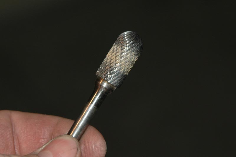
You can use that, or take your new oil pump and smear a thin layer of gasket sealer on the mating face of the oil pump with your finger and then slide the pump onto the cap. Be careful not to get any sealer into the oil pump. Remove the cap and the sealer will show you where the opening in your new pump is. I used a scribe and traced out the hole profile on the cap, and then wiped all of the sealer off of the pump and the cap. This has to be done fairly quickly so the sealer doesn’t dry on the pump or cap. Now that you have your hole profile you need to get out the die grinder or drill and the burr-bit. All of the porting I have ever done has been accomplished with an old beat up dewalt electric drill. It is hard on the bearings in the chuck of the drill to have a side load on them as they are not meant for that, so you may want to use an old drill or a die grinder. Whichever you choose, you do want a variable speed so you can slow it down or speed it up while shaping. I always use a burr cutter with straight sides and a ball nose. These bits seem to work the best for me; however you may want to use a different style bit. It is all personal preference I think.
Lately things are getting pretty bad, and everyone likes to save a little money whenever possible, so with that in mind I thought it would be cool to share some performance modifications that can be done at home.
Jake Shannon......
Most of these mods are things that are done with the engine disassembled, before it leaves for the machine shop. Some are easy, and some are tough, but you never learn if you don’t try!
Simple home oiling modifications:
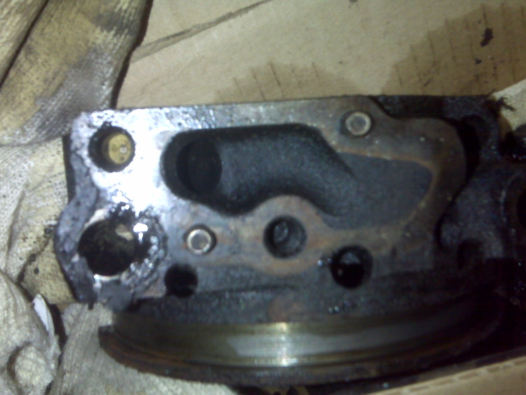
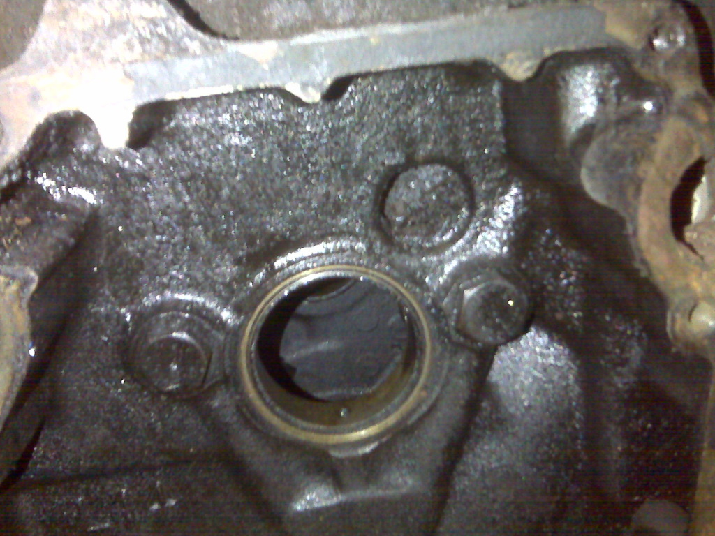
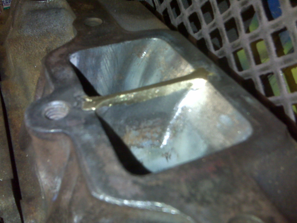
One thing that seems to be over-looked a lot is the rear main cap oil restriction. This is simple to fix. The stock cast valley in the rear main cap where the oil flows in from the pump is horrible for oil flow. The opening in the cap is only about half as big as the opening in the pump, creating a blunt face for the oil to slam into and have to squeeze around. Once you remove the oil pump you will see a shadow left behind from the oil outlining where the cap needs to be opened up.
When shaping the opening in the cap you want to have a smooth transition all the way down into the hole. I started by hogging out the material so the pump hole lines up. I worked from the exit hole side to the other blending so the angle down into the hole stayed uniform. Ideally I think you want the very end farthest from the exit hole to be shallow and taper in the hole as shown on the photos. After that is all taken care of you want to smooth out the casting and blend all of the sharp edges around the hole into a smooth radius. Smooth out the rest of the rough casting. Run the drill wide open and use a light touch when polishing the taper down into the hole. Next you want to clean up the angle in the hole where it goes down into the block. These were drilled out in two different directions and the drill points didn’t really line up, so there are two “shelves” in the hole that need to be blended out. Smooth out the one shelf using the burr bit form the oil pump side of the cap. Once that is smoothed out, flip the cap over and do the same thing to the other one from the block side of the hole. This takes care of the rear main cap. This isn’t a bad job, but there is patience involved, and you have to hold on the drill so the bit doesn’t catch and jump out of the hole marking the oil pump mating surface. A tip is to slow the drill down some when porting by the edges. When you run it wide open it is harder to hold on to the drill.
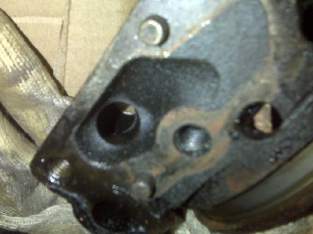
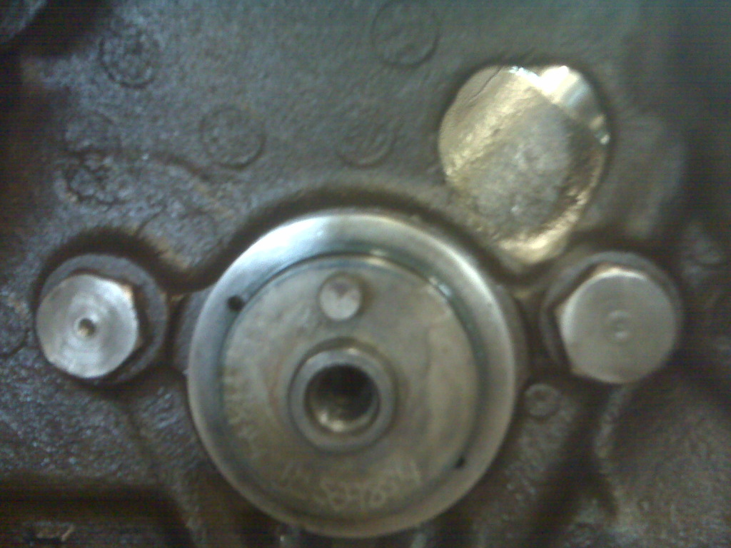
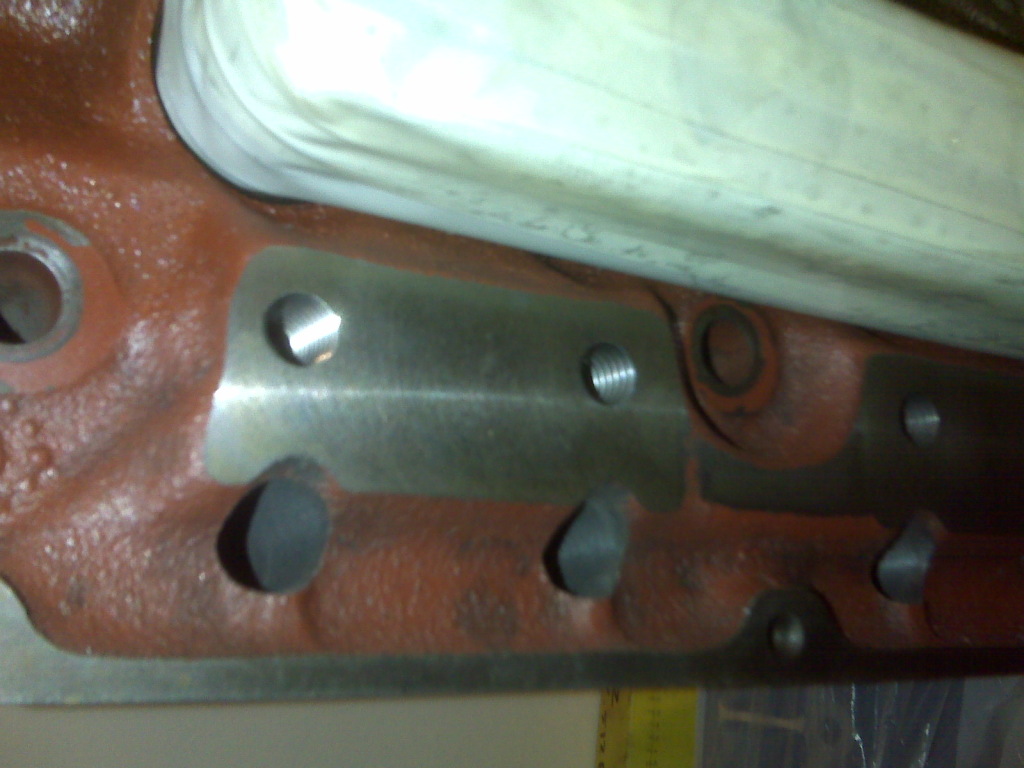
The next simple oiling mod is to open the oil drain hole in the front of the block behind the timing chain. This is pretty cut and dry. Just use the burr bit and open up the bottom of the hole until it looks like an upside down tear drop, as shown below. This takes all of five minutes to accomplish.
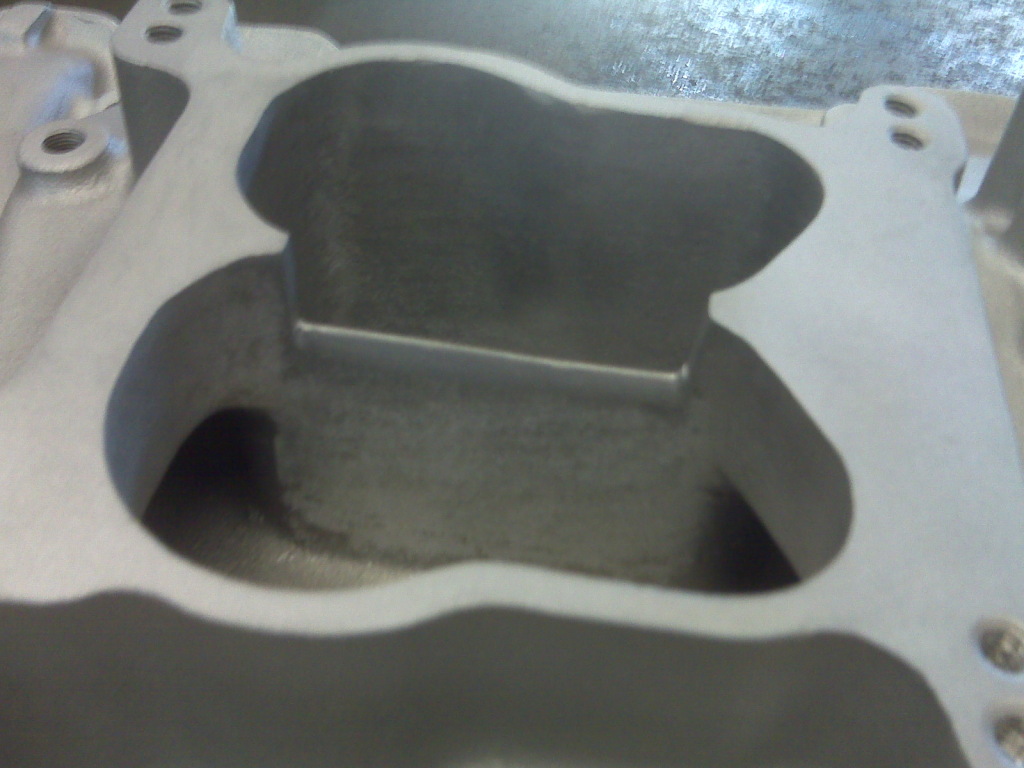
Home Intake Modifications:
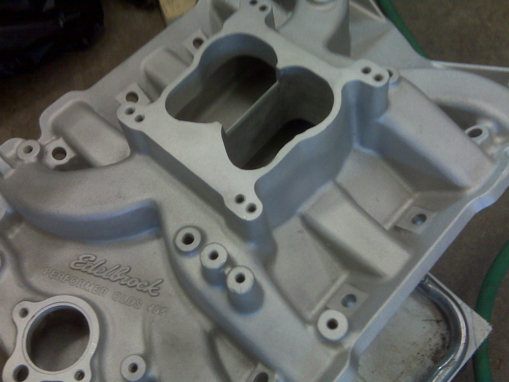
With an Olds, your choices of intakes are limited. If you run the Edelbrock Performer (which I have), you have your low end torque, but sacrifice top end power. If you run a Torker, you sacrifice some low end torque for some extra top end power. The Performer is a lot more of a street friendly manifold I feel, and Oldsmobile’s are big, heavy cars, so I personally prefer the low end torque to get it out of the hole. One simple way to get a little more top end power out of a performer is to cut the center divider down about ¾” to allow better air/fuel distribution through the entire manifold. This is easy to do as well. I used the trusty old drill and a burr bit for this as well. I started by marking each side of the center divider where the radii end and it becomes straight. At an angle I started cutting away material from each side of the divider and just kept working my way down. There are two good things about cutting on angle. One, it is easier on the drill and you can remove material faster. Two, this creates a knife-edge on the center divider so the air/fuel flows around it better. Once I was done with this I ran the drill wide open and lightly cleaned up the casting down into the plenum.
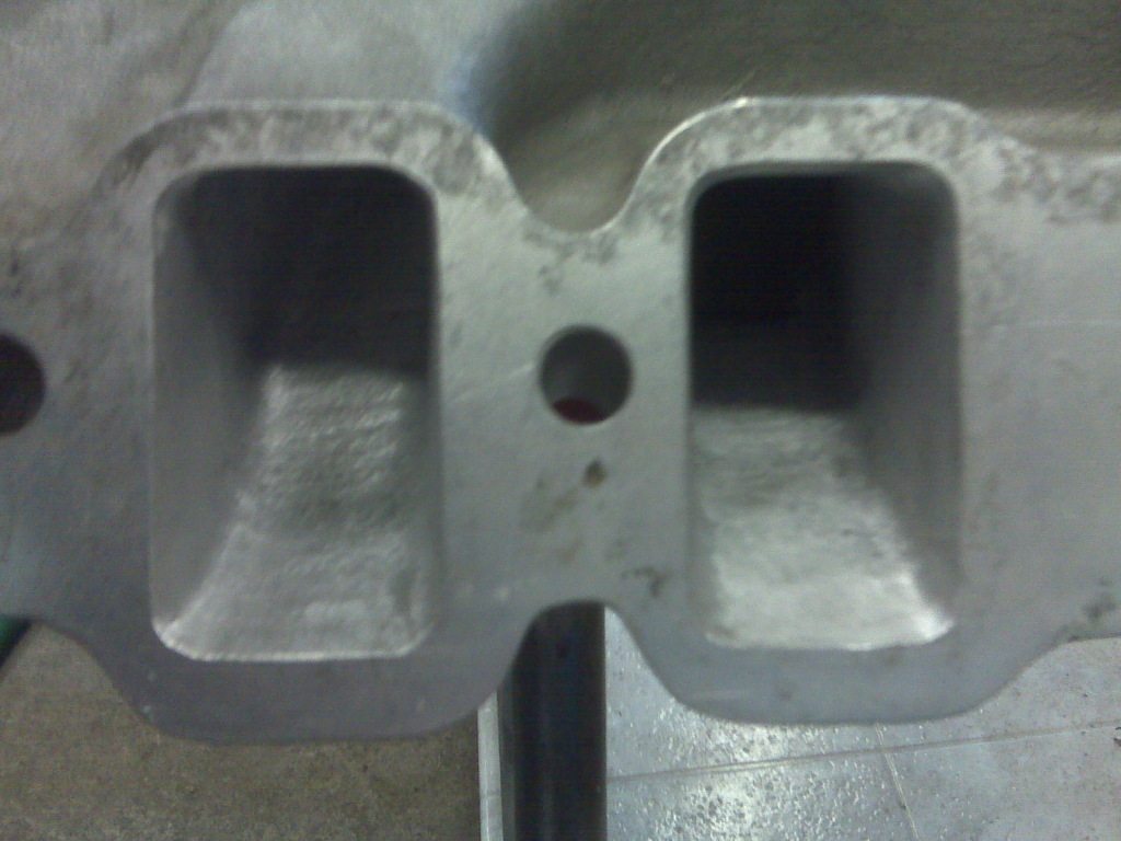
Next I gasket match ported the intake runners. I used a black Sharpie marker and colored around ports first so I could see my line later. You can also use layout die. Next I lined up and taped the gasket to the intake and used a scribe to mark the opening of the gasket on the intake. I removed the gasket and proceeded to do the same thing to the other side of the manifold. Now what you want to do is use the burr bit and open the runners up to the scribed marks you made. Use a long shank bit and taper the runners to the scribed marks from as up far into the intake as possible. Run the drill fast and press lightly when cutting. When cutting out the opening you want to slide the bit back and forth or up and down in the opening so it doesn’t catch and make a big mark. This seemed to be the best way to get the cut uniform and straight on the line. Remember, you don’t want these polished to a mirror finish. When you are done it will still be a little rough, but not as rough as a stock casting. If you get the runners too smooth, you can actually loose horse power due to lack of air/fuel atomization. The small amount of roughness is good to produce a little bit of turbulence and also creates a surface air layer that the air/fuel mix can glide along into the cylinder. This takes a while to finish, and once again, remember, you have to be patient. The second you get in a hurry you make mistakes. If you are getting tired of porting, just set the drill down and walk away for a little bit.
Home Head Modifications:
A lot of people run roller rockers, and here is one thing you can do at home to help cut the cost down. If you are going to the trouble of running roller rockers, you might as well open up the stud holes from 5/16”-18 to 3/8”-16 or 7/16”-14 for strength. You will need a drill press to do this, but a lot of people have one or know someone who does. Do not hand drill and tap these holes, as they cannot be crooked. The cool thing is, if you are re-tapping to 3/8”-16, 5/16” is the tap drill, so all you have to do is chuck up a 5/16” drill bit and cut the threads out before you tap. You only want to drill 1” deep (from the very tip of the drill bit), so fit a drill stop to your bit, or pay close attention to the depth indicator. There is a trick when it comes to tapping these holes using the drill press, or you can hand tap them using a hole block to keep the tap straight. Chuck the tap up into the drill press and on a lower speed, turn the drill press on. Be sure you are centered on the drilled hole before you attempt this. Keep in mind this is probably for a more experienced person on a drill press. What you want to do is turn the drill press off and quickly plunge the tap into the hole. The tap will start straight and as it cuts it will slow to a stop. Undo the chuck and then use a wrench to finish tapping the hole. Once that is done take the tap out and use a bottom tap or get another tap and grind the leading edge off to get total treads to the bottom of the hole. Repeat this sixteen times. It takes a little while to finish this, but it definitely save money at the machine shop.
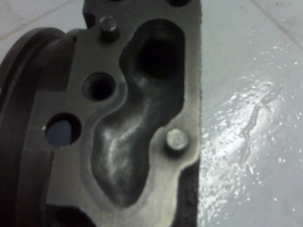
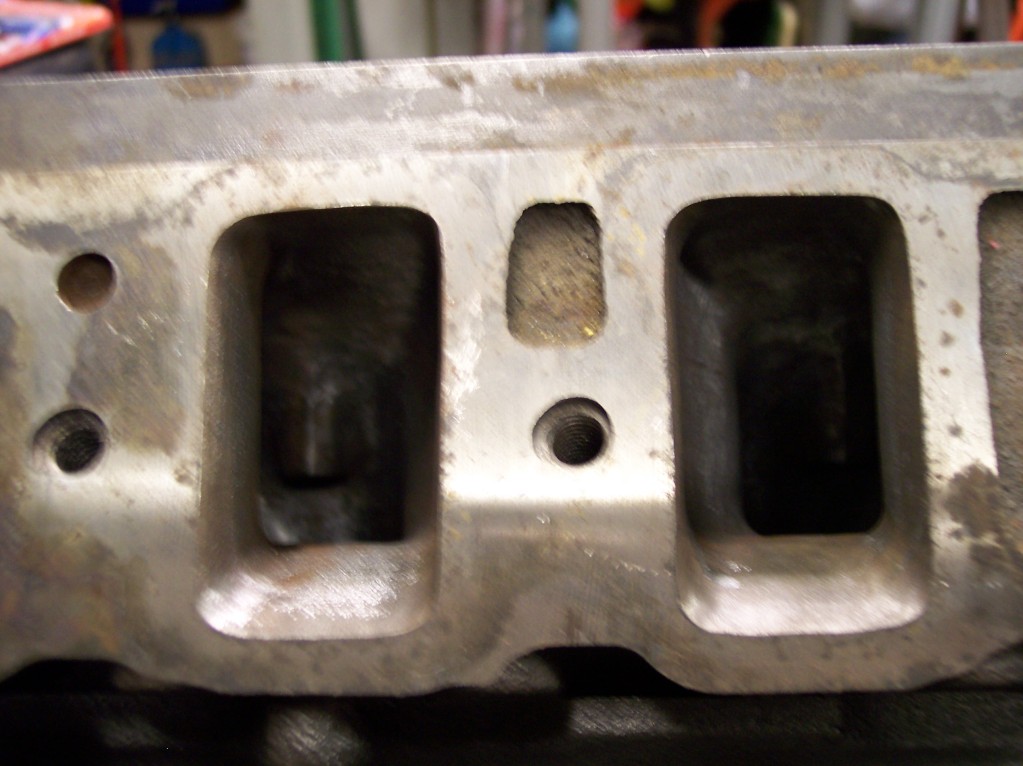
Head porting is a science, but if you understand what you need to do it really isn’t too hard. It is time consuming, but once again, this will save you a ton of cash at the machine shop. You can do this with filling the heat crossover and the exhaust center divider, or without.
I will start with filling the crossover and brazing or welding the divider, as this will need to be done before porting. If you are going to do both, do the center divider first, as the head will get red hot on the divider, and you don’t want to screw up your crossover alloy.
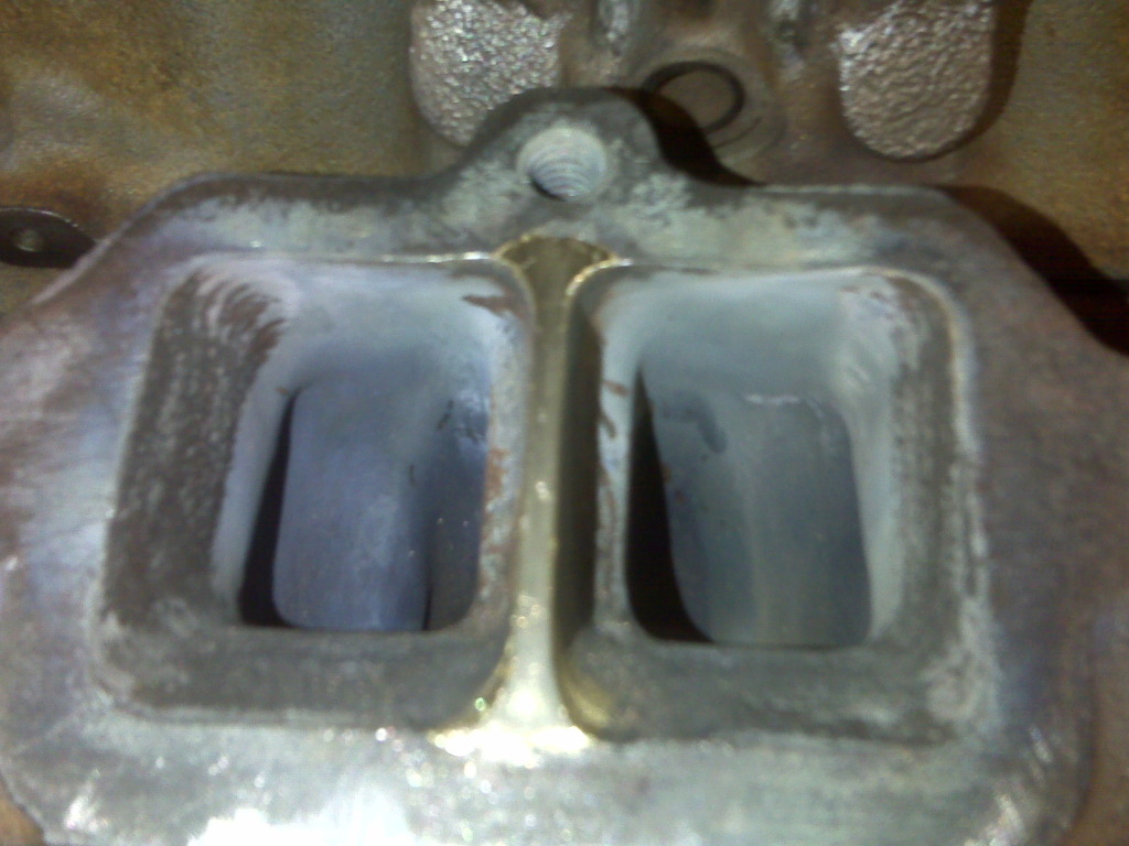
Brazing the center divider on the exhaust face of the heads is what it is. You just need to build up the center divider so it completely separates the exhaust ports. You can braze it or weld it. The heating and cooling procedures are pretty strict with cast iron though, so you have to be careful. I never had any luck welding cast iron with a nickel rod, so brazed them. I heated them up slowly with the torch first and then set them on the wood stove so they would cool slowly. This is kind of hard to clean before brazing as the cast iron is porous and soaks up dirt. You can tell mine were not completely clean as there is air bubbles in the brass. Once it’s done you just have to shape the brass to match the port outlet and then smooth out the face some. When you take the heads to be machined, just have them take a skim cut on the exhaust face to true it up.
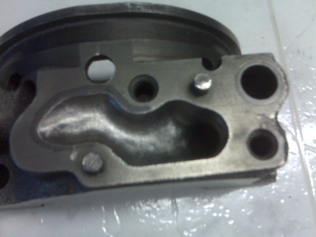
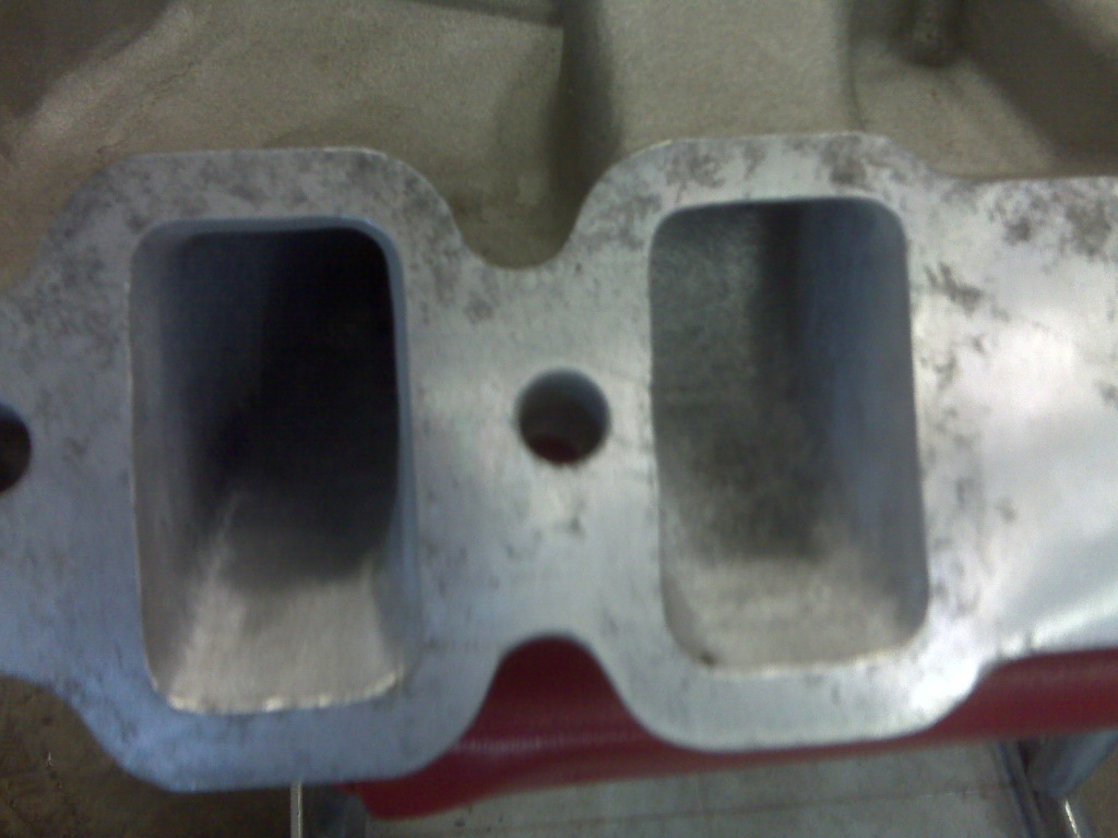
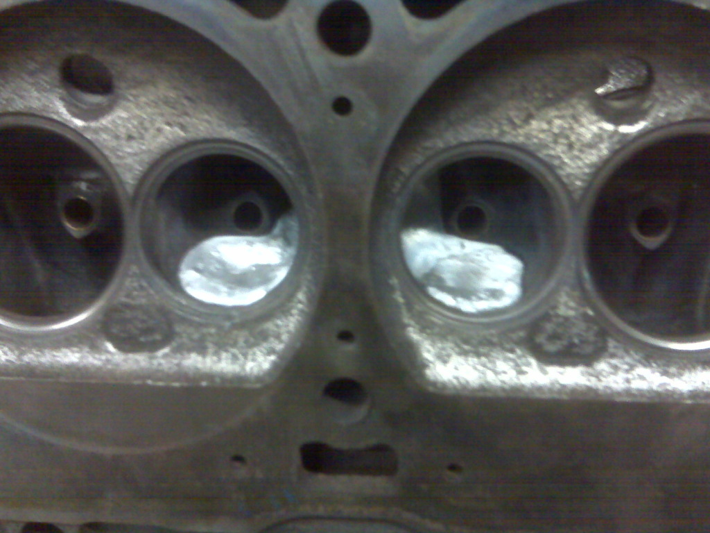
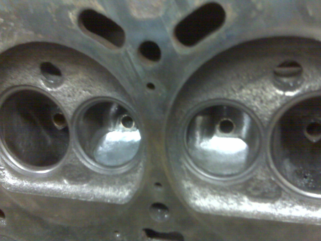
If you look in the ports you can see the finished filled heat crossover.
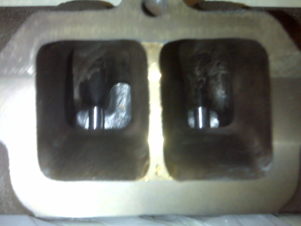
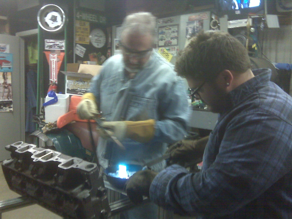
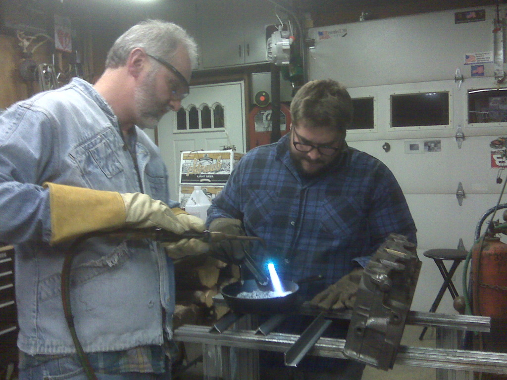
Filling the heat crossover is something that intimidates people, but it really isn’t too bad. First, you have to get material to fill it. You can buy an ingot of zinc/aluminum alloy (ZA12) from M&J Proformance or I think Dick Miller might have it as well, or you can use old pistons. Old pistons take more heat to melt and they soak up gas and oil, so you have skim off all of the crap once it melts. I would recommend using ZA12. It was $27 shipped when I bought it. It’s clean, and it melts nicer. I went to the hardware store and bought a cast iron skillet to melt it in. We used a torch, but propane can also be used. This is a two person job, so my dad stepped in and manned the torch. I set the heads on the top of the wood burner in the garage to heat them up a little before the pour, but I don’t think that it is absolutely necessary to do that. These two dissimilar materials never actually bond together, but the shape of two holes blending into one keeps it in there. Don’t get me wrong, it isn’t actually loose in there, it just doesn’t melt in to the cast iron. I drilled two holes in a piece of steel and bolted it on the intake side of the head blocking the crossover hole. We set the head up on a set of horses and tilted it back so the deck is slightly up. The reason for this is so the alloy can flow up and out into the roof of the exhaust ports filling in the big divot beside the valve guide boss. Once the alloy is melted into a puddle it is about 900*F, so use extreme caution when handling the skillet, or whatever you use to pour it. I had to use 3 shop rags and welding gloves to pick it up. It actually turned the inner shop rag black it was so hot. Make sure the alloy is completely melted. You will know as it will flow around the pan like water, but it has a high surface tension and looks like the terminator. It is pretty cool. You can either pour the molten ZA12 in an exhaust port or right into one of the exhaust valve holes. I poured it into the exhaust valve hole. You have to do this one continuous pour. Pour the alloy in and it will fill up the center crossover hole and then start to fill the back of the bowls. It will start to run out of the exhaust seat on the side you are pouring first, but keep pouring it in until you are sure both ports are completely full. Do not worry about the valve seats as the alloy wont stick and will come right off. I let the head sit for a while before I moved it and then let them sit over night to cool slowly before I did anything else to them. After they are cooled down, you just have to shape the back of the bowls and blend the alloy up into the roof of the port for a smooth entry. Be careful not to let thin pieces of alloy in there as small pieces can dislodge. You will be able to tell when you are porting it, how thin it is.
Now that we are through with all of that we can port the heads. Once again, all of this takes a while to finish, but it definitely saves money, and your cast iron heads should out flow a set stock cast Edelbrock heads. This is a street/strip port, nothing extravagant, but it will definitely help, even if you don’t fill the crossover or build the divider up. Same as I said before with the intake, you don’t want the runners to be super smooth and polished, but you want the rough castings smoothed out.
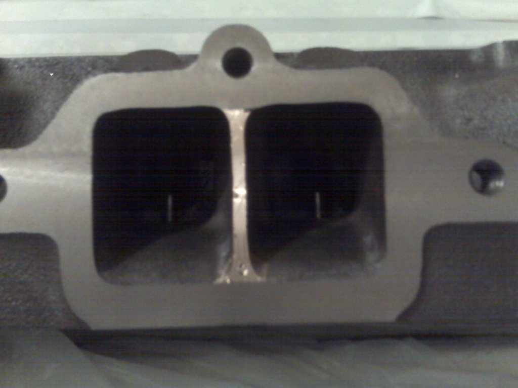
Starting on the intake runners, use the same method with the intake gasket marking the port openings. Start by opening up the runners to the marks you made on face. Blend these in to the runners toward the valve guides. Smooth out the bottom of the ports, but don’t remove any excess material. The back side of the bumps where the head bolt or pushrod holes go through (these will stick out from the side of the port) have a sharp edge on them. Round off this edge. The port roof will have a large bump in it for where the rocker studs holes come down into the head. Grind down this bump until it is flat. Sometimes you will break into the rocker stud hole, but that isn’t a big deal. Just use thread sealer on the studs and it is fine. Next you want to tear drop the valve guide boss. What this means is you want the leading edge of the boss to be a sharp point and taper out around the valve guide instead of a blunt boss for the air/fuel mix to run into. Next come the bowls, which is the area behind the valve opening. Smooth and shape them round to help the mix get out of the valve. Be careful and hold on to the drill when working by the valve seats. Porting should always be done before your machine work, as no matter what, somehow you will always end up nicking a valve seat a little. Blend the areas beside your tear-dropped guide up into the bowls. Next are the exhaust ports. The same method applies to the valve guides and the bowls as the intake side. The exhaust ports have what’s called an EGR bump of the roof of each port. You want to grind these down until the roof is flat just like bump in the intake ports. Note: Some A heads have the EGR bump, and some don’t. If you have A heads without it, that’s just one less thing you have to do to them! Open up the top of the outlet of the exhaust ports a little, between 1/16” and 3/32”. This will help the exhaust flow out into the header better. Always get a good valve job and have the valves back cut to help flow as well. This porting method works on all modern Olds V8 heads, 260-455.
STROKING, PORTING & POLISHING:
My $0.02... If you want to stroke your engine, just save the 400 and put it in the garage. start with a 455. there is no replacement for displacement. mathematically you are starting out ahead with more cubes, plus the 455 has a bigger bore which helps unshroud the valves for better flow and cylinder fill. There are also a lot more cam choices for a 455 as they have the 39* lifter angle vs. the 45* lifter angle on the 65 400. If you wanted it to look more stock, you can use the A heads on it, but you have to drill out the pushrod holes due to the change in lifter angle.
Porting heads is a cheap way to increase some power. keep in mind you dont want to "pollish" the intake side. you want it to have a little bit of texture as it creates enough turbulence to atomize the fuel and air. If you polished the intake side the fuel will want to puddle. You dont want to go overboard on your port job for a street car. I will add tear dropping the valve guides and removing the bumps in the intake port roof and egr bumps on the exhaust side. Filling the center divider on the center ports helps for power too as it helps the exhaust scavenge correctly. You can also fill the heat x-overs, but that isnt ideal on a full blown street car that gets driven a lot.
If you are running a stock intake and stock exhaust manifolds, all that port work isnt going to do all that much, especially with that little 4GC carb on there.
Sorry, I kind of went a little crazy there. Forgive my ramblings. haha Jake Shannon
I've always matched the intake gasket to both the head and intake manifold about 2" in - you want a smooth transition! Leave the middle of the intake port alone, unless there's flash, and just knock it out, if so! The intake bowl is important - smooth about 2"in, and yes. teardrop the guide area, blending to the seat. You can port the exhaust all the way out, carbon won't stick!
Back-cutting the valves, [shallower cut from the seat, after lapping] is good for some more HP, on any head! Might cost a little more, but worth it!! Rickman